
System for operational verification of vibration sensors with amplifiers. The program controlling this measurement offers two modes:
Calibration mode based on the comparative method.
This mode uses
- BK8305 standard accelerometer, the BK 2635 preamplifier,
- BK11075 standard vibration exciter and LV103 power amplifier,
- HP34401A multimeter to measure the output signal from the standard sensor,
- another HP34401A multimeter to measure the output signal from the sensor for measuring the internal resistance of the measured sensor – measuring and lifting coils
- and the HP33120 generator for vibration excitation.
The following sequence of steps is performed: First, the values describing the measurements (who, when, why, etc.) and the measurement method (e.g., whether or not to measure the internal resistance of the sensor) are entered. The resistance of the lifting coil and the current of the lifting coil is then measured, subsequently, using a control loop (multimeter evaluates the output of the standard and regulates the generator so that after the conversion, the output is equal to the desired value). Then individual values of acceleration, distance, resp. velocity is red, always after stabilization. It is done for all calibration points. The measured values are converted to exact calibration points. The deviation and the relative deviation are calculated. Finally, the maximum deviation is determined and checked to be less than the permissible deviation. The program prints the calibration sheet, saves the calibration values in a file (for additional evaluation), and makes a record in the calibration database. It ends the measurement.
Absolute calibration mode of the VBM010 amplifier.
The measuring of the amplifier is principally based on a serial interconnection of a pair of amplifiers. The first one converts the AC voltage from the input (usually generated by the vibration sensor) to an output DC voltage in the range of 0 to 10V. Subsequently, this voltage is transformed into a 0 – 20 mA or 4 – 20 mA current output. Thus, the output current is a function of the output voltage, not the input voltage. This test uses the HP33120 generator to drive the input, the HP34401A multimeter to measure the output signal from the amplifier, and another HP34401A multimeter to measure the output current signal from the second amplifier.
The following steps are performed: First, values describing the measurements (who, when, why, etc.) and the measurement method are entered. Subsequently, with the help of a generator at a constant frequency, the individual values of the input AC voltage are changed according to the given table. Each time output values, DC voltage, and current are red. It is done for all calibration points. Relative voltage deviation and relative current deviation are calculated from the measured values. Subsequently, whether the maximum deviation found is less than the permissible deviation is evaluated. The program prints the calibration sheet, saves the calibration values in a file (for additional evaluation), and records them in the calibration database. It ends the measurement.
The program is prepared in the TestPoint development environment. An example of input window is:
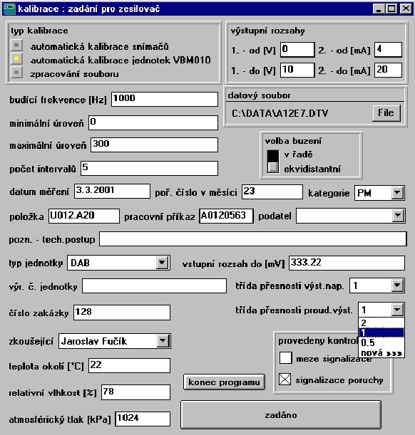
Request here more information.